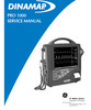
GE Medical DINAMAP PRO 1000 patient monitor service manual


GE Medical DINAMAP PRO 1000 patient monitor service manual
TABLE OF CONTENTS
SECTION 1 INTRODUCTION
1.1. Scope of Manual........................................................................................1-1
1.2. Manual Changes .......................................................................................1-2
1.3 Service Policy ............................................................................................1-2
1.3.1 Extended Warranties .................................................................................1-2
1.3.2 Assistance .................................................................................................1-2
1.3.3 Service ......................................................................................................1-3
1.3.4 Service Loaners.........................................................................................1-4
1.3.5 Repair Parts ..............................................................................................1-4
1.3.6 Replacement Accessories .........................................................................1-5
1.4 Product Description ...................................................................................1-5
1.4.1 General Description...................................................................................1-5
1.4.2 Storage Batteries.......................................................................................1-6
Table 1-1 Specifications..........................................................................................1-7
SECTION 2. PRODUCT DESCRIPTION
2.1. Introduction ................................................................................................2-3
2.2. Product Configurations ..............................................................................2-3
2.3. Controls, Indicators, and Connectors.........................................................2-3
2.3.1. PRO Monitor Rear Panel Connections ......................................................2-4
2.3.2. Front Panel Controls and Indicators...........................................................2-5
2.4. Host Port Connector (rear panel) ...............................................................2-7
2.4.1. Pin Assignments ........................................................................................2-7
2.5. Compatible Parts .......................................................................................2-8
2.6. Specifications.............................................................................................2-9
2.6.1. Power Requirements .................................................................................2-9
2.6.2. Environmental ............................................................................................2-9
2.6.3. Mechanical.............................................................................................. 2-10
2.6.4. NIBP ....................................................................................................... 2-10
2.6.5. Temperature ........................................................................................... 2-10
2.6.6. SpO2....................................................................................................... 2-11
2.6.7. ECG........................................................................................................ 2-12
SECTION 3. PRINCIPLES OF OPERATION
3.1. Introduction ...............................................................................................3-3
3.2. Overall Principle Of Operation ..................................................................3-3
3.2.1. Nellcor SPO2.............................................................................................3-3
3.2.2. Cuff Blood Pressure (BP) and Pulse .........................................................3-3
3.2.3. Alaris Oral and Rectal Thermometry .........................................................3-4
3.2.4. ECG with Heart Rate and Respiration .......................................................3-4
iii
3.2.5. Host Communication Ports........................................................................3-4
3.3. Functional Description ..............................................................................3-5
3.3.1. PSU PWA..................................................................................................3-5
3.3.2. Mains Converter Module ...........................................................................3-6
3.3.3. Main Board ................................................................................................3-6
3.3.4. Keyboard PWA..........................................................................................3-7
3.3.5. ECG PWA .................................................................................................3-8
3.3.6. Pneumatic Control .....................................................................................3-8
3.3.7. LCD Assembly...........................................................................................3-9
3.3.8. Printer (Optional) .................................................................................... 3-10
List of Figures
3-1 General System Diagram .............................................................................. 3-12
SECTION 4. GENERAL MAINTENANCE
4.1. Introduction................................................................................................4-3
4.2. Configuring the PRO 1000 Monitor for the First Time................................4-3
4.2.1 Unpacking and Preparation for Installation................................................4-3
4.2.2 Set the Date and the Clock........................................................................4-5
4.2.3 Parameter Level Functional Testing ..........................................................4-6
4.3. Periodic Maintenance ................................................................................4-7
4.3.1. As Required...............................................................................................4-7
4.3.1.1 Integrity of Cuffs and Hoses ..................................................................4-7
4.3.1.2 External DC Supply and Battery ............................................................4-7
4.3.1.3 Cleaning of Accessories ........................................................................4-7
4.3.1.4 Long Term Storage................................................................................4-8
4.3.2 Annual Procedures ....................................................................................4-8
4.4. Care of Storage Batteries ..........................................................................4-9
4.4.1. Procedures for First Use............................................................................4-9
4.4.2 Battery Charging........................................................................................4-9
4.5 Safety Resistance Testing...................................................................... 4-12
4.6. Alarm Code Interpretation ...................................................................... 4-14
4.6.1. System Failures...................................................................................... 4-14
4.6.2. Hardware Errors ..................................................................................... 4-15
4.6.3. Parameter Failures ................................................................................. 4-15
4.6.3.1 ECG/RESP/TEMP Errors ................................................................... 4-15
4.6.3.2 NIBP Messages.................................................................................. 4-15
4.6.3.3 Temperature Messages...................................................................... 4-16
4.6.3.4 SpO2 Messages ................................................................................. 4-16
4.7. Service Mode Operation......................................................................... 4-16
4.7.1 SpO2 Tests ............................................................................................ 4-19
4.7.2 NIBP Tests ............................................................................................. 4-20
4.7.2.1 Leak Test............................................................................................ 4-21
4.7.2.2 NIBP Calibration Check ...................................................................... 4-23
iv
4.7.2.3 Pressure Recalibration ....................................................................... 4-24
4.7.2.4 Overpressure Test.............................................................................. 4-25
4.7.3 EKG Tests .............................................................................................. 4-27
4.7.4 Temp Tests ............................................................................................ 4-28
4.7.5 Recorder Tests ....................................................................................... 4-30
4.7.6 Battery Tests .......................................................................................... 4-31
4.7.7 Test Failsafe Logic ................................................................................. 4-32
4.7.8 Keypad LED Test ................................................................................... 4-33
4.7.9 Keypad Key Test .................................................................................... 4-33
4.7.10 Sound Test............................................................................................. 4-33
4.7.11 Turn off the System................................................................................ 4-33
4.8 Service Mode Exit................................................................................... 4-33
Chapter 4 Appendices
Test Record ......................................................................................... Appendix A
Monitor Configuration Log ................................................................... Appendix B
SECTION 5 ASSEMBLY DRAWINGS & ELECTRICAL SCHEMATICS
Assembly Drawings (Monitor Assembly & Disassembly)
Front Case 1 ......................................................................................................5-1/2
Front Case 2 ......................................................................................................5-3/4
Rear Case 1.......................................................................................................5-5/6
Rear Case 2.......................................................................................................5-7/8
Electrical Schematics
ECG Board 315589........................................................................ 5-9 through 5-18
Main Board 315592...................................................................... 5-19 through 5-42
Power Supply Board 315593 ....................................................... 5-43 through 5-52
Keyboard ........................................................................................................ 5-53/54
Probe Warmer ................................................................................................ 5-55/56
schematic diagrams included in 109 pages
Keywords: pro;ge medical;dinamap;1000
File Size: 10 MBytes
| Embed: |
|
 pro;ge medical;dinamap;1000
282578822
16.95
maxxtor
Fresh Download
Available!
pro;ge medical;dinamap;1000
282578822
16.95
maxxtor
Fresh Download
Available!